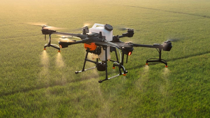
We design purpose-built, rigorously tested technologies that enable devices to sense, think, connect and act intelligently to improve people's daily lives.
Spotlight on Industrial
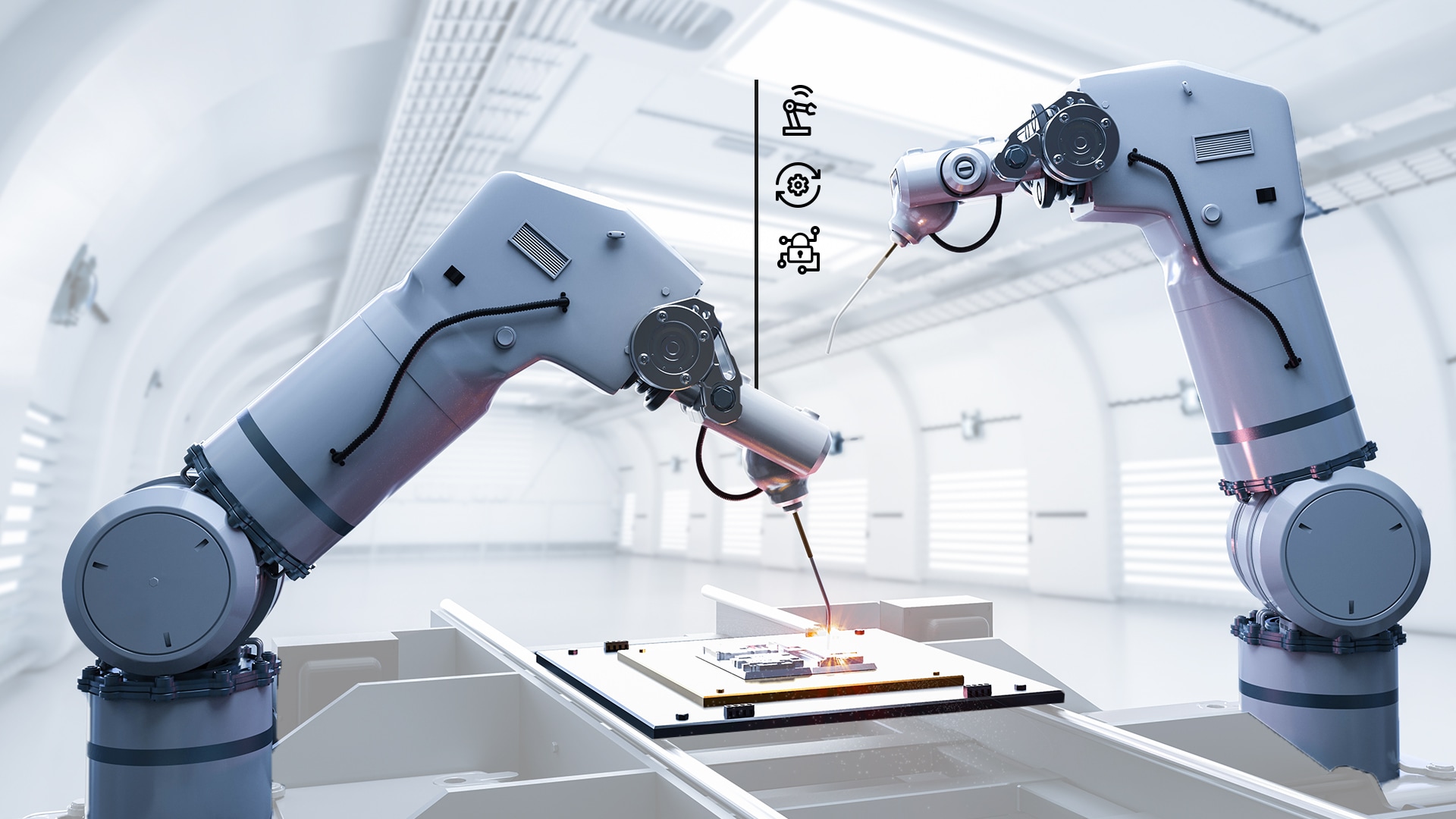
Reshaping the Factory Landscape
Enable flexible automation to master complexity in the smart factory.
Start Designing Today with NXP
Ready to gain access to everything NXP?
The reasons for registering keep growing. Sign up today and unlock a premium experience on NXP.com.
"We have a vision of a world that anticipates and automates to meet all of our needs."
-

Kurt Sievers
President and Chief Executive Officer
Meet the NXP leadership team
Wij zijn NXP. 我们是恩智浦. Nous sommes NXP. 우리는 NXP입니다. Wir sind NXP. 私たちはNXPです. We are NXP.
Enabling a Better, More Sustainable World
As our digitally-enhanced world is evolving to anticipate and automate people's needs, NXP strives to engage, protect and respect our relationship with the wider world.
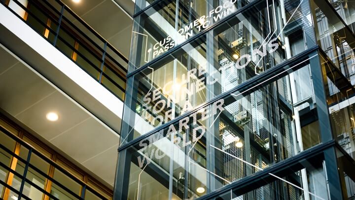
Long-Term Success With R&D Investment
Investing in solutions that drive long-term, profitable growth, free cash flow and robust capital returns to our owners; enabling our customers' success.
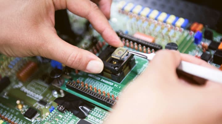
Decades of Expertise and Innovation
Our technology enabled the first words relayed from the moon and ever since we’ve been accelerating the breakthroughs that advance our world.
Bright Minds. Bright Futures.
NXP team members create breakthrough technologies that advance our world. We're looking for innovative, passionate, and talented people like you to join our team. The future starts here.
Scroll down